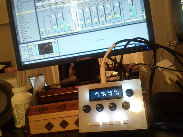
Last year I built a small MIDI controlled polyphonic synthesizer called KittySynth using a 72MHz LeafLabs Maple microcontroller board, an Audio Codec Shield from Open Music Labs, and some C++. I had originally had some ideas to try to build something like this by abusing the timers and PWM duty cycles on a 16MHz Arduino Mega I have, but quickly realized there was no way on earth I could build what I wanted to with the small amount of resources on an Arduino. The ARM based STM32 chip on the Maple had just enough resources available to create an 8-voice polyphonic wavetable synth, which I should write about sooner or later.
Anyway, while researching for that project I found out that someone actually has created a perfectly viable synthesizer based around a 20MHz ATMega chip (as in the Arduino) called the Shruthi-1. I thought this was a perfect opportunity to go through the steps of actually building a proper synth of the sort I would someday like to design, so I ordered the Shruth-1 4-Pole Mission Kit, and decided to put it together from scratch.
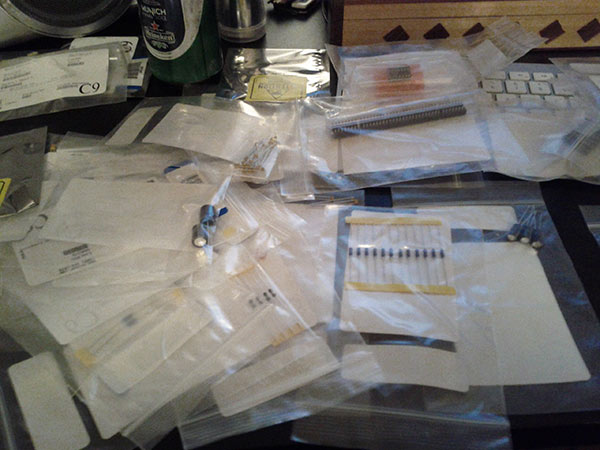
Shruthies are only really offered as kits you put together, they’re about $180 Canadian, and come from France. If you want a real, working, and fun synth for not a lot of money and can use a soldering iron, it’s probably the way to go.
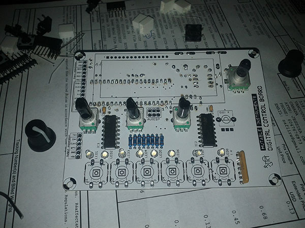
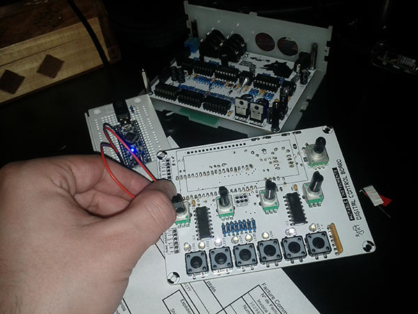
Olivier Gillet, the designer of the Shruthi, is pretty inspirational to me, but how did he design an awesome synth around a little 20MHz ATMega chip? First thing, is that the Shruth-1 4-Pole Mission is a hybrid digital-analog monosynth. The synth is divided into two PCBs, the top PCB is the digital control board, which contains the ATMega chip, LCD, knobs, and buttons. It is running software responsible for handling MIDI, generating the digital wavetable oscillators, envelopes, LFOs, reading the knobs. There are 20 pins connecting it to the bottom PCB that primarily contains the analog filter, but also has the power regulator, MIDI and audio inputs and outputs.
Having an analog filter is a common cause for a synth to be monophonic, ie. only one voice or note at a time. This is because in order to be polyphonic an analog synth would need separate circuitry for oscillator, envelope, and filter for each possible voice that could sound at once, making it much more expensive for each voice. There are paraphonic synthesizers which can assign a note to more than one oscillator and sound them simultaneously, but uses only one envelope and one filter. The Shruthi-1 does something similar with its duophony mode. Since it has two oscillators it allows you to play two notes at once, the first is assigned to Osc1, and the second to Osc2, however they are both enveloped and filtered together.
Digital Board
Shruthi-1 has two 8-bit digital oscillators, and either a square or triangle sub oscillator, or a click generator to create nice transients during a note’s attack. The main and sub oscillators have a vibrato setting, the main oscs are also able to be detuned separately, and have a PWM control.
Looking at the code, the Shruthi-1 generates its 8-bit oscillators in a few different ways, I can see code for rendering pure wavetables with interpolation, some code where it is waveshaping a static wavetable, some for interpolating two wavetables together, and some which outright generates a signal in real-time.
The sub osc or click/noise generator is sent straight to a digital mixer for summation, while the two main oscs
enter a modulator first. The modulator is where a significant amount of character is introduced in the synth.
The default algorithm in the modulator is a simple balance control between the two oscillators, but there are
many other algorithms such as:
- Mixing with balance
- Syncing - Osc2’s phase resets when Osc1’s does
- Ring Modulation - Multiply and scales
- XOR - Combines the two Oscs with bitwise xor
- Fuzz - Osc1 & 2 are shaped by tanh(), like a soft clipper
- 4 or 8 bit sample rate reduction
- Bit Crusher
- Duo - Let’s Osc1 & 2 play two different notes at once
- More I haven’t figured out :)
Analog Board
Next in the signal chain, the output received in the digital mixer is converted to 10MHz/1-bit audio. This means the audio can be represented by a pulse width modulated square wave. A PWM waveform is literally only ever on or off, hence the 1-bit depth, but it can be used to represent any fractional voltage between 0GND and whatever is your high voltage. For example if you attach an LED to a PWM output and the square wave is at 100% duty cycle it will shine the brightest it can, but if you alternate between turning it on and off for exactly half the time, 50% duty cycle, it will shine half as bright. It is really turning on and off really fast, but that is imperceptable to us most of the time. Duty cycles from 0% to 100% can be created to represent the internal 8-bit digital values from 0-255, and in PWM form, the audio can be sent electrically to the filter board for processing.
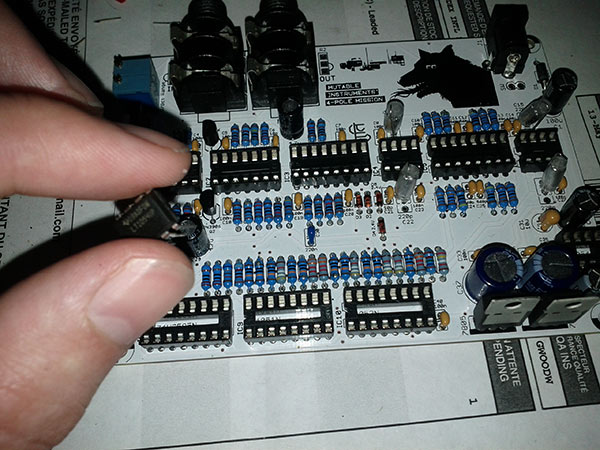
The filter board on my Shruthi-1 is a 4-pole ladder filter, which is essentially four 1-pole filters connected in series. The current is delayed in phase by 90° by each 1-pole component, usually caused by the reactance of a capacitor in a simple RC filter, and I assume something similar must be going on here. After going through all four stages, the phase has gone around to 360°, and so is back where it started. Variably mixing its output back into the first pole’s input causes the sick resonance ladder filters are known for because the phase lines up again and reinforces frequencies in a loop at the filter’s cutoff frequency.
Other synths using laddder filters are Moogs and the TB-303, though they are constructed differently. The Shruthi also let’s you use the output at 1,2, or 3 poles which affects the slope of the stop-band. You can also use the audio input in the back of the synth to apply the filter to whatever external sounds you want, provided you hold the envelope open.
Building it
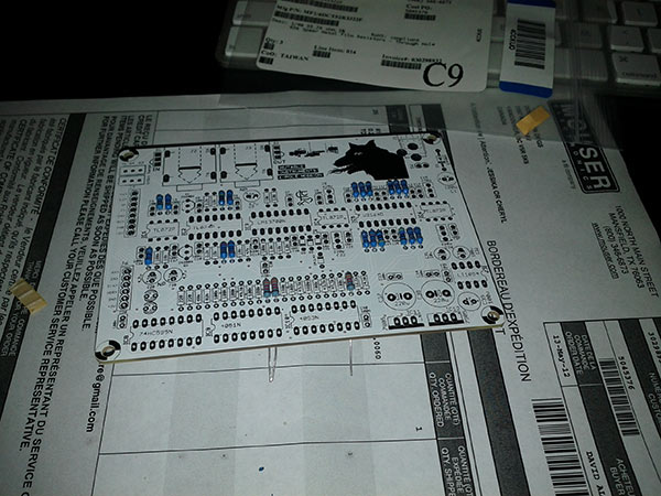
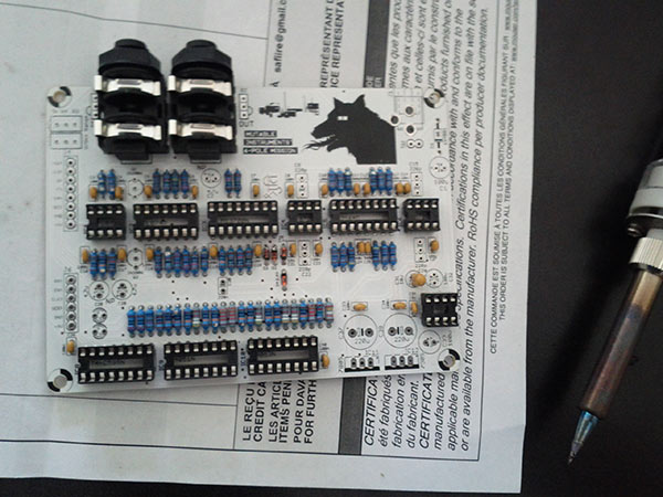
The kit was actually pretty easy to assemble, and I spent a few hours per day on it and had it done over a weekend. Since I don’t have one of those fancy stands with clips to hold the boards for me, it was important to solder all the components in order of height, which meant doing all the resistors first, etc. That way when you flip it over to solder the joint it will be held in place by resting on your work surface.
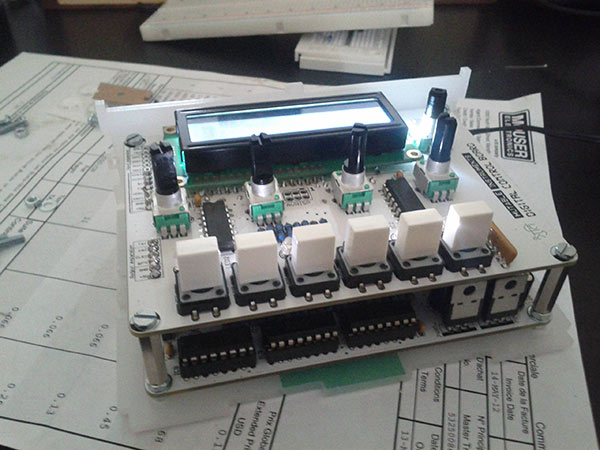
I chose to do the filter board first, as it seemed like the hardest to do, but it was quite easy. The digital board was a little tricky with its LCD screen probably being the hardest part out of the whole project. A found the case kind of sucky, mine looked like it was cut out of the end of a huge piece of plastic, which had ugly green print on some of it, luckily it was on the bottom, and it was missing a screw hole on the top face.
The 20 pins which connect the top and bottom boards are sort of haphhazardly connected, because they don’t reach so well, but they are firmly together, even if not perfect, and I haven’t had a problem with it.
Sound
So far, I’ve found that the Shruthi-1 makes one crazy analog sounding bassline, so here is an example of the track I wrote after I finished the build. :) I used the Shruthi-1 for bass, and a few other parts here and there.
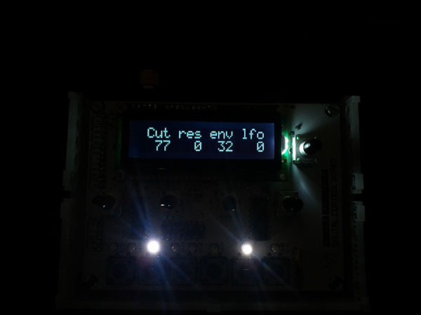
Finished Pic!
